Before you start
Get everything printed and ordered first. The PCB takes the longest to arrive.
- Gather the tools: 3D printer, soldering iron, multimeter, screwdrivers, a saw, a drill, two taps and CA glue. Full tools list →
- Order the PCB early: send the Gerbers to any PCB maker. Electronics →
- Order the hardware from the parts list.
- Print all parts. Every file is available as 3MF and STL and they open in any slicer. 3D prints →
- Push steel pins into the printed screws, as they otherwise snap easily. Use a 3 mm drill to clean out the holes first, then push or hammer the steel pins in.
- Clean up the prints, remove support and clean threads with the taps M10 × 1.5 and M8 × 1.25.
Build the frame
Two 3030 extrusions, front and back, bolted between the left and right end brackets.
Printed parts


Hardware
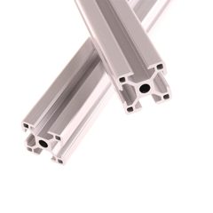 23030 extrusion, 250 mm (cut from 600 mm)
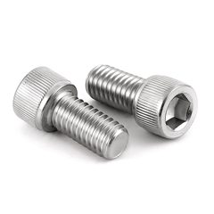 4M8 × 20 mm socket head screws
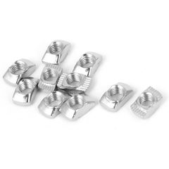 7M6 T-nuts + M6 screws
Prepare the 3030 extrusions
- Cut two 250 mm pieces of extrusion. File the cut ends square and deburr them.
- Drill the centre bore at each end with a 6.8 mm bit, about 20 mm deep.
- Tap the bore with the M8 × 1.25 tap. Use a little oil and back the tap out every turn to clear chips.
Assemble
- Bolt the left and right end brackets to both extrusions with the M8 × 20 mm screws: one per end, four in total.
- Check the frame sits flat and square before tightening fully.
Y axis
The two Y sliders carry the X axis front to back on the 150 mm rods.
Printed parts


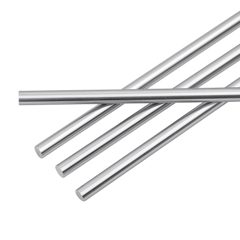
Press in the linear bearings: two per slider
- Slide one of the 8 mm rods through the linear bearing first. The rod keeps the balls in place; without it they can fall out, especially if the bearing needs tapping in.
- Stand the bearing upright on a flat surface and push the Y slider down over it. It should be a snug fit.
- Press in the second bearing the same way, so each slider holds two, four in total.
- If it needs more force, tap it in lightly, with a piece of wood or similar between the hammer and the bearing.
Fit the 150 mm rods
- Slide a 150 mm rod part of the way into the end bracket, from the back: the side away from the stepper motor mount. It is a snug fit.
- If the rod will not go in, clean out the hole in the bracket with an 8 mm drill.
- Before pushing the rod all the way in, slide the Y slider onto it. Check it is the right one for this side: 1.3 Y-Axis Slider, Left on 1.1 End Bracket, Left, and 1.4 Right on 1.2 Right.
- Push the rod all the way in, until it is flush with the mounting hole by the stepper motor.
- Repeat for the other side.
X axis & tool carriage
The X sled runs left to right on two 300 mm rods and carries the tool holder.
Printed parts


Hardware
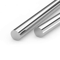 28 mm rod, 300 mm
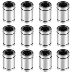 —LM8UU linear bearings
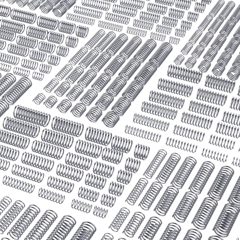 setSprings, 5 × 25 mm
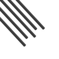 —Carbon rod, 5 mm (cut to length)
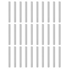 4 + 2Steel pins, 3 × 35 mm and 3 × 20 mm
- Press the LM8UU bearings into the X sled and slide it onto the two 300 mm rods.
- Fit the rod ends into the Y sliders.
- Mount the tool holder on the sled.
- Fit the pressure screws with their springs and caps. The carbon rods guide them; the springs press the tool onto the stone.
- Clamp the tool in the wide vise with the clamp screws. Print four of one version: 2.5 tightens by hand, 2.6 with an Allen key.
To be completed Bearing count, carbon-rod lengths and the number of pressure screws.
CoreXY belt drive
Two motors and one belt loop move the sled in X and Y together.
Hardware
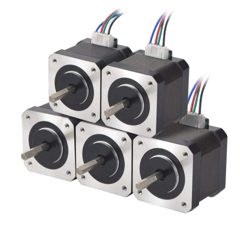 2NEMA 17 stepper motors
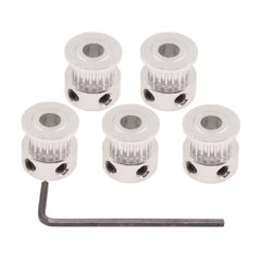 2GT2 pulley, 20 teeth
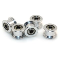 8GT2 idler wheels, toothless
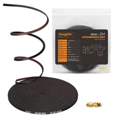 1GT2 timing belt, 6 mm
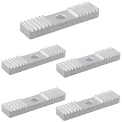 2GT2 belt clamps
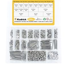 8M3 × 18 screws (motors)
- 4 + 4M3 × 18 screws + nuts (tension)
- 2 + 2M3 × 18 screws + nuts (clamps)
- Mount the two motors with the M3 × 18 screws and fit a 20-tooth pulley on each.
- Fit the idler wheels.
- Route the belt around the pulleys and idlers. To be completed
- Fix both belt ends in the belt clamps on the X sled, under the tool holder.
- Tension the belt with the M3 tensioning screws until it is taut and twangs, not slack.
To be completed Belt route diagram, motor corners and belt length.
Stone holder
The stone sits in front on the 3030 and does not move.
Printed parts


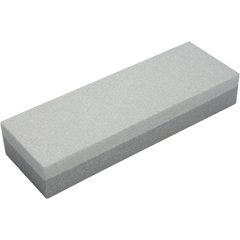
- Fix the stone holder to the 3030 extrusion with T-nuts and M6 screws.
- Slide the 300 mm rod through to hold the stone holder in place.
- Lay the stone in the holder and tighten the stone clamp screw.
Water pump
A printed peristaltic pump on the third motor drips water onto the stone.
Printed parts


Hardware
- 1NEMA 17 stepper motor
- 1GT2 pulley, 20 teeth
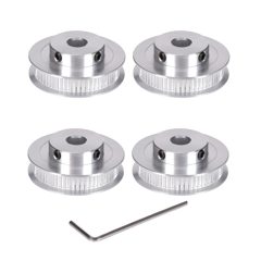 1GT2 pulley, 60 teeth
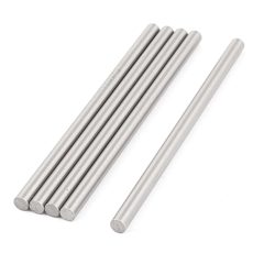 1Steel rod, 5 × 60 mm (shaft)
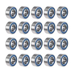 6Ball bearings 5 × 10 × 4 mm
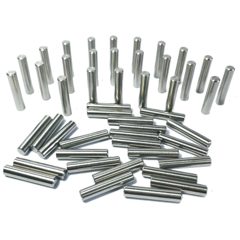 —Steel pins, 5 × 25 mm
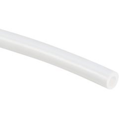 —Silicone tube, 3 × 6 mm
- 6Magnets (optional)
- Put the ball bearings on the 5 × 25 mm pins and fit them between the two rotor halves: they are the rollers that squeeze the tube.
- Mount the rotor on the 5 mm shaft in the pump body.
- Fit the 60-tooth pulley on the shaft and drive it from the motor's 20-tooth pulley. To be completed
- Lay the silicone tube around the rotor and hold it with the four tube clamps.
- Close with the cover and the two tightening nuts.
- Optional: glue magnets into the side frame and the pump frame so the pump stays docked to the machine.
Water disperser
An articulated arm that brings the tube over the stone.
Printed parts


Hardware
- —Silicone tube, 3 × 6 mm
- —Carbon rod, 5 mm (pipe holder)
- —Steel pins for the clamp screw
- The base comes off the printer with its swivel ball already inside; print them together, the ball cannot go in afterwards. Add the knee joint, then the arm.
- Fix the disperser base with the disperser base clamp screw (6.3), and lock the knee joint with the knee joint clamp screw (6.5).
- Run the tube from the pump along the arm and hold it with two or three tube clips, outlet over the stone.
Electronics box
One PCB carries the ESP32, the three drivers and every connector.


Hardware
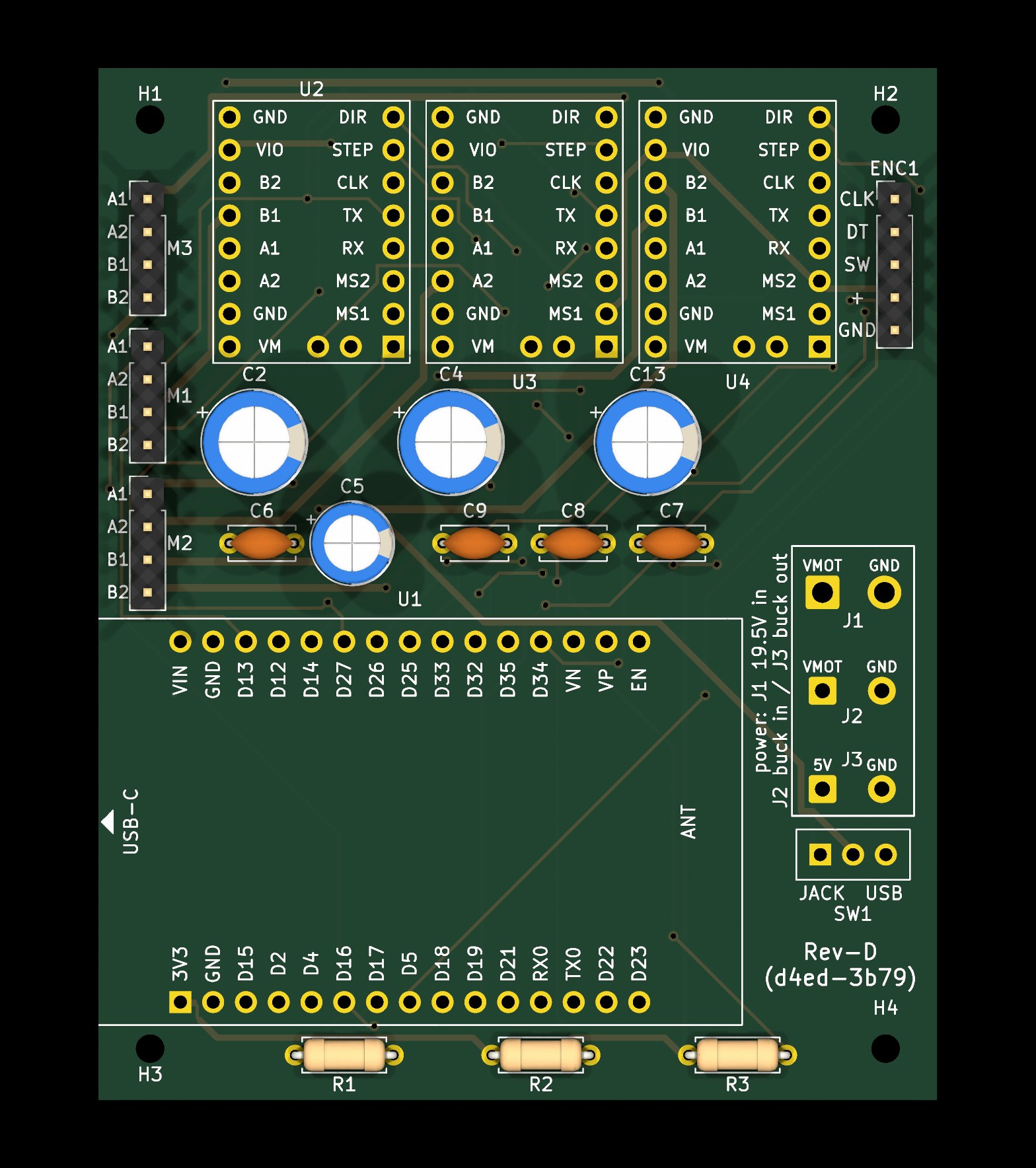 1AutoSharpener PCB
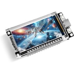 1ideaspark ESP32, 1.9" LCD
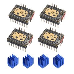 3TMC2209 drivers
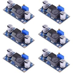 1LM2596 buck module
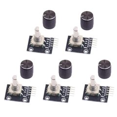 1KY-040 rotary encoder
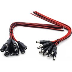 1Barrel socket pigtail
 4M2 × 5 screws
- Solder the board: capacitors, resistors, slide switch, header sockets and pin headers. Full component list on the parts list.
- Set the buck module to 5.0 V with a meter, with nothing connected to its output.
- Check the ESP32 and each TMC2209 against the pin labels printed on the board: right way round, every pin in its own socket. Then push them in and fit the driver heatsinks.
- Screw the board into the electronics box with the M2 × 5 screws.
- Fit the encoder in the box and push on the knob; close with the lid.
- Mount the box on the 3030 extrusion with T-nuts.
USB-C arrow, and its pin labels must line up with the labels printed on the board (VIN on VIN, 3V3 on 3V3). Do the same for each TMC2209. A module turned round or shifted by one pin puts the supply on the wrong pin and is destroyed.Cabling
Everything plugs or solders into the board; nothing is wired point to point.
Printed parts

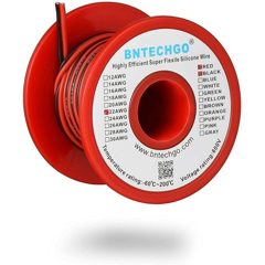
| From | To | Notes |
|---|---|---|
| Gantry motor A | M1 | Pins A1 A2 B1 B2: coil A on pins 1–2, coil B on 3–4 |
| Gantry motor B | M2 | |
| Pump motor | M3 | |
| KY-040 encoder | ENC1 | CLK, DT, SW, +, GND, straight across |
| Barrel socket | J1 | Centre (red) to VMOT, the square pad; sleeve to GND |
| Buck input | J2 | VMOT to IN+, GND to IN− |
| Buck output | J3 | OUT+ to 5V, OUT− to GND |
- Plug in the three motors and the encoder.
- Solder the barrel socket pigtail into J1, and the buck module into J2 (input) and J3 (output).
- Fit the barrel plug from the pair onto your 19.5 V laptop charger.
- Tidy the motor cables with the cable holder.
To be completed Which gantry motor is A and which is B.
Optional
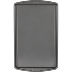
Lift the machine and stand it in a baking sheet, so the water can circulate endlessly.
Printed parts

- Glue the four stands (7.3) underneath the left and right end brackets with CA glue, two per bracket. They lift the machine clear of the tray.
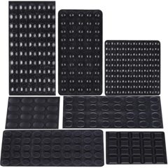
- Stick a rubber foot under each stand.
- Stand the machine in a baking sheet and add water. The pump draws from the tray and the run-off from the stone drains back into it, so the water circulates endlessly.
First power-on
The ESP32 can be powered from the barrel jack or from its own USB-C port. The slide switch SW1 on the board picks which one.
How the JACK / USB switch works
| SW1 | ESP32 powered by | Motors powered by | Use it for |
|---|---|---|---|
JACK | The charger, through the 5 V buck module | The charger | Normal sharpening. No USB cable. |
USB | The USB-C cable only | The charger, if plugged in | Flashing firmware and testing from a computer |
Normal use: powered from the jack
- Make sure no USB-C cable is plugged into the ESP32.
- Set SW1 to JACK.
- Plug in the charger. The screen comes on and the self-test runs.
- To switch off, unplug the charger.
Flashing or testing: powered from USB
- Set SW1 to USB.
- Plug in the charger. The screen must stay dark: that proves the ESP32 is not powered from the jack. If the screen lights up, SW1 is on JACK. Unplug the charger, fix the switch and start again.
- Straight away, plug in the USB-C cable. The ESP32 starts from your computer. Flash the firmware or test now. Firmware →
- To finish, unplug the charger first, then the USB cable.
First start
- Flash the firmware over USB, as above. Firmware →
- Unplug the USB cable, set SW1 to JACK and plug in the charger.
- The self-test checks the drivers, motor supply, stall lines and encoder. Every row must read OK.
- Home the machine: the carriage finds its corner by stall detection, no end-stops needed.
- Clamp a tool, pick a pattern and start. Every run starts at 25 mm/s; turn the knob to speed up.
kStallThreshold in lib/Board/Board.h of the source code; the comments next to it explain how.Safety rules
Read before anything is powered.
kMotorCurrentMa.